Robot Gripper Definition:
A gripper is a Printing. (in certain presses) one of a number of fingerlike devices forgripping a sheet and transferring it to or from the printing surface... We will be using our gripper to grip a soda bottle and transport it to one of our teammates so that he can satisfy his quenching thirst.
Definition of Robot Gripping Project:
All the key phases for modeling a VEX Clawbot robot in Autodesk Inventor software will be reviewed. Modeling the robot in Autodesk Inventor consists of assembling parts from the virtual kit of parts library. The key phases in the required workflow are reviewed in this overview video.
students will learn how to use Autodesk Inventor project files to organize file location. An overview of project files and how to set the active project file is shown. The completed robot is opened in Autodesk Inventor. With the file opened, the view manipulation tools are demonstrated.
The students learn that the structural frame members have square holes that have to be aligned correctly. Assembling the parts using the iMates attached to each hole simplifies the process by reducing the number of clicks required. This workflow enables you to snap each part into its correct location.
The students use standard parts to assemble the frame. Autodesk Inventor provides standard parts such as nuts, bolts, and washers. They can be placed in an assembly using Content Center. In this project, the standard parts are provided and are constrained to the base frame using the iMate workflow used previously.
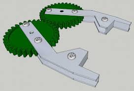
The students simplify the placement of wheel parts by creating a subassembly. To reduce the time required to create a wheel assembly, the parts are demoted into a subassembly. With the wheels in place, a 60-tooth gear is added between the wheels, and motion constraints are added to the gears
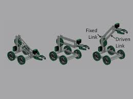
The students add the remaining parts to complete the robot assembly. The claw is constrained to the claw arm. Braces are added to provide additional support to the vertical channels.
The students use Inventor Studio to create rendered images and an animation of the robot.
The student reviews the workflow required to model the robot. Modeling the robot requires a number of different workflows in Autodesk Inventor including:
students will learn how to use Autodesk Inventor project files to organize file location. An overview of project files and how to set the active project file is shown. The completed robot is opened in Autodesk Inventor. With the file opened, the view manipulation tools are demonstrated.
The students learn that the structural frame members have square holes that have to be aligned correctly. Assembling the parts using the iMates attached to each hole simplifies the process by reducing the number of clicks required. This workflow enables you to snap each part into its correct location.
The students use standard parts to assemble the frame. Autodesk Inventor provides standard parts such as nuts, bolts, and washers. They can be placed in an assembly using Content Center. In this project, the standard parts are provided and are constrained to the base frame using the iMate workflow used previously.
The students simplify the placement of wheel parts by creating a subassembly. To reduce the time required to create a wheel assembly, the parts are demoted into a subassembly. With the wheels in place, a 60-tooth gear is added between the wheels, and motion constraints are added to the gears
The students add the remaining parts to complete the robot assembly. The claw is constrained to the claw arm. Braces are added to provide additional support to the vertical channels.
The students use Inventor Studio to create rendered images and an animation of the robot.
The student reviews the workflow required to model the robot. Modeling the robot requires a number of different workflows in Autodesk Inventor including:
Robot Gripping Video:
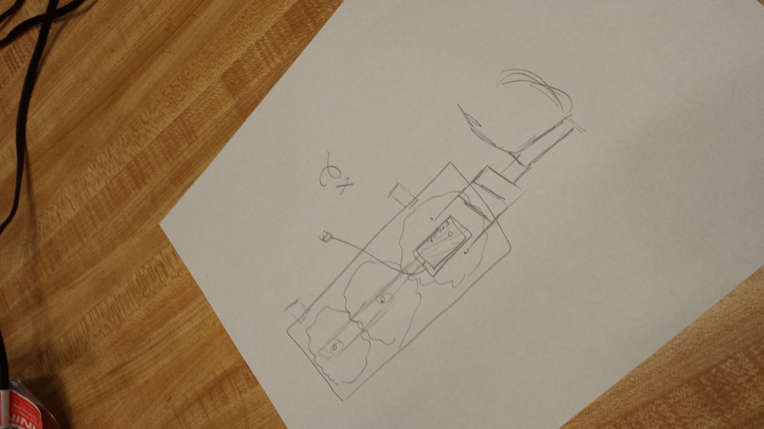
Our Gripper Ideas:
|
|
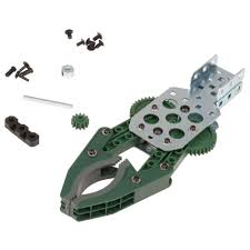
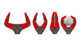
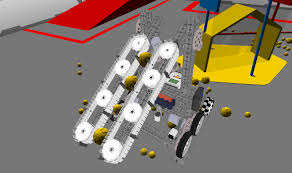
Our Double Gripper Design:
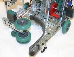
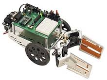
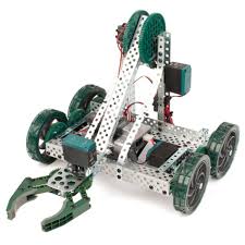
Our Robot:
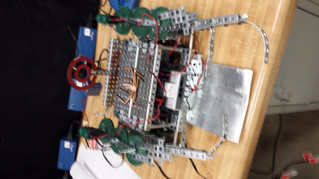
OUR ROBOT!!!!!!!!
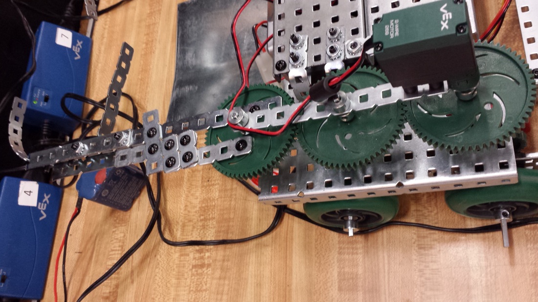
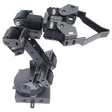
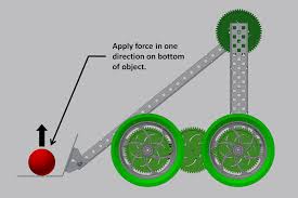
This is the arm of the robot. It will help to pull in the object.
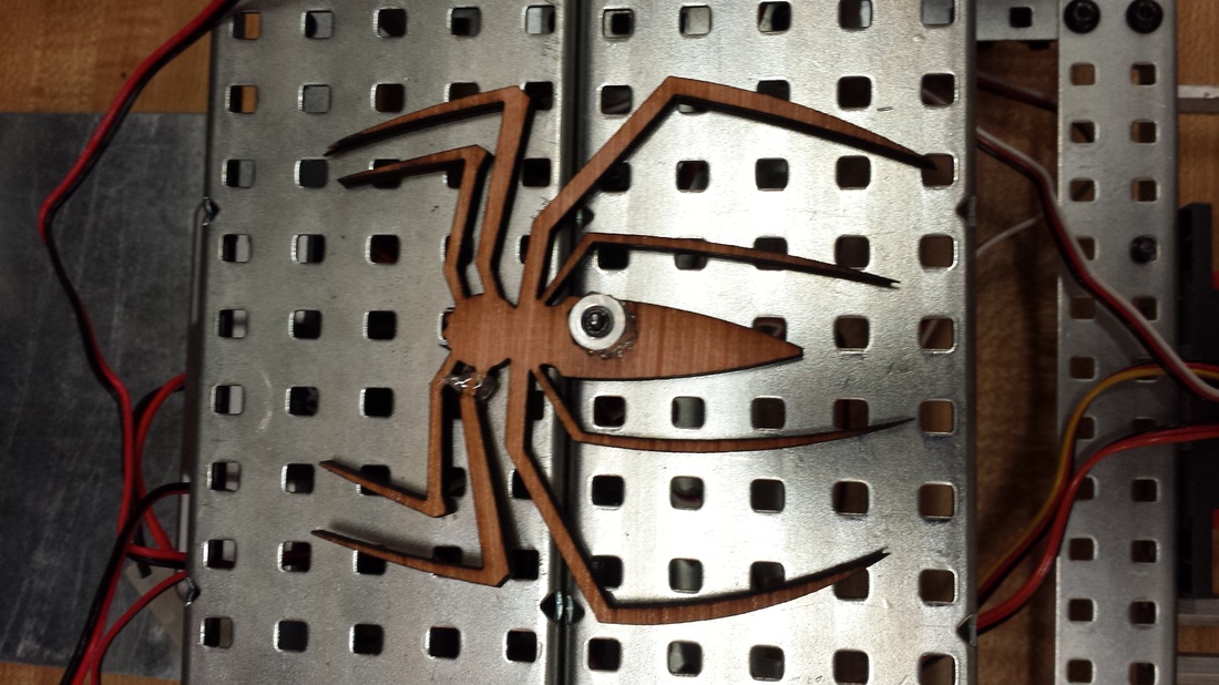
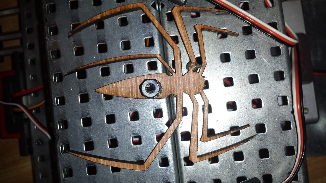
This is just our symbol for the spider bot. It's pretty cool.
|
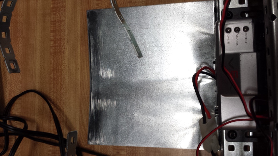
This is the scooper. It will help to scoop the object.
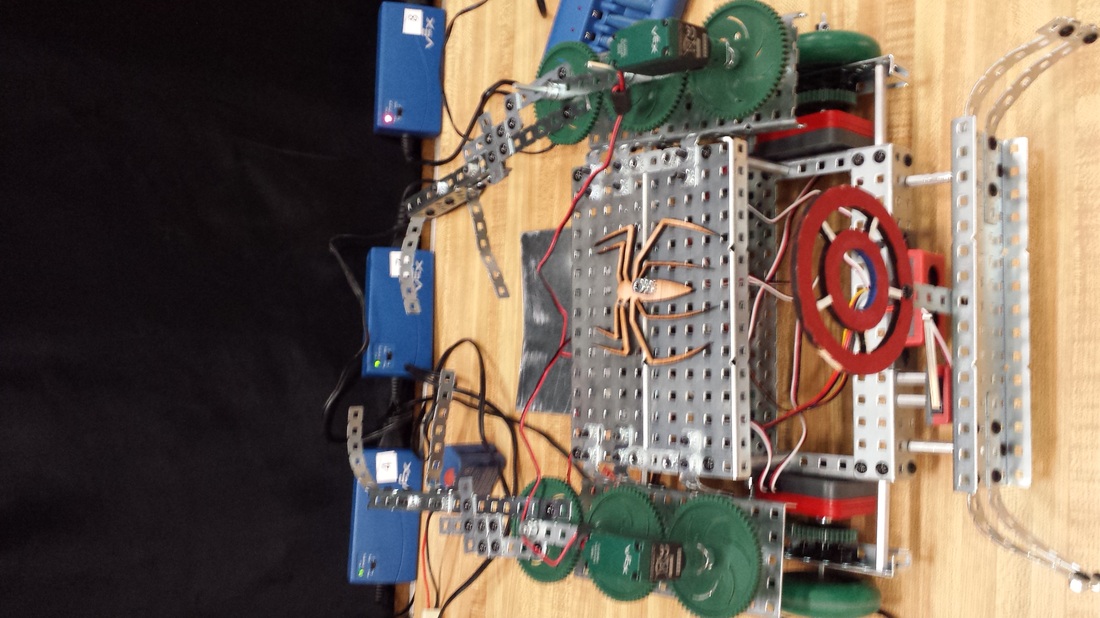
This is our whole amazing robot'
|
Our Video:
Our laser cut program & picture:
| spiderman_(2).dwg |
